Restoring the vintage Casio VL-5 keyboard
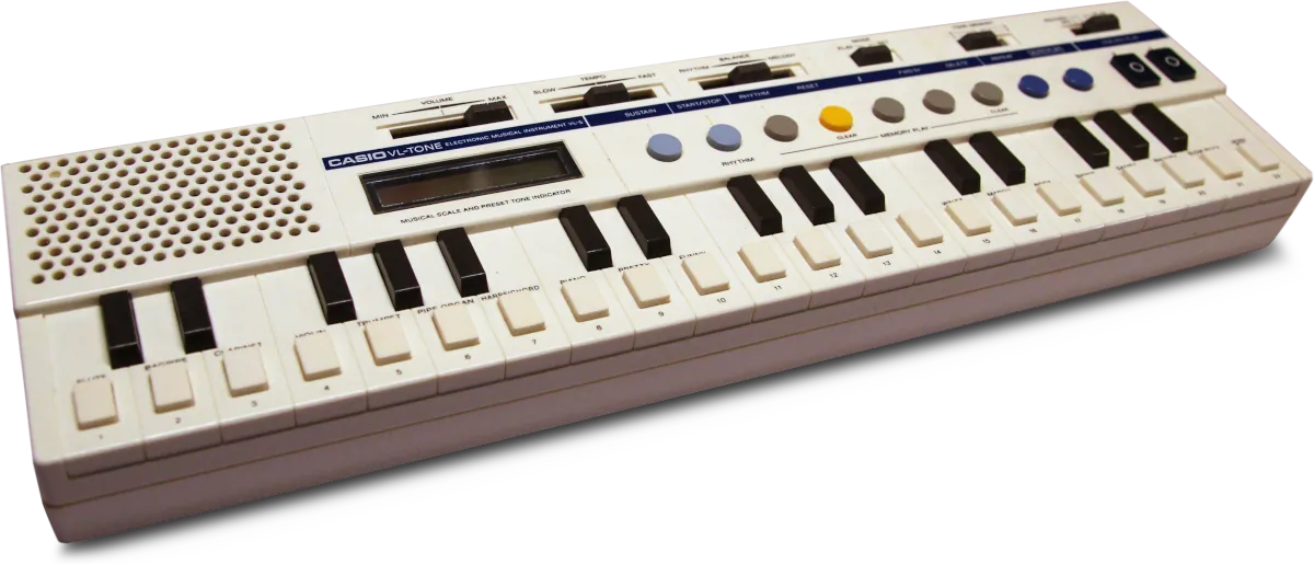 For years, I'd been itching to get my hands on its older sibling, the Casio VL-1, famously featured in Trio's song "Da Da Da". However, I recently stumbled upon this VL-5 on mercatinomusicale.com (an italian-only market like reverb.com) at a pretty reasonable price. It was listed as non-functional, and I just couldn't resist it.
These keyboards, manufactured in Japan starting in the late '70s, carved out a unique niche, bridging the gap between a toy and a serious instrument: a truly fascinating hybrid.
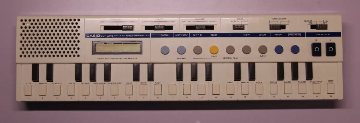
Unlike the VL-1, this VL-5 is an upgrade in some respects, boasting 4 voices of polyphony and a 3-octave range. However, it’s a significant downgrade in another crucial area: it lacks the ability to modify sound synthesis and envelope parameters (ADSR). This is precisely what makes the VL-1 a true mini-digital synthesizer.
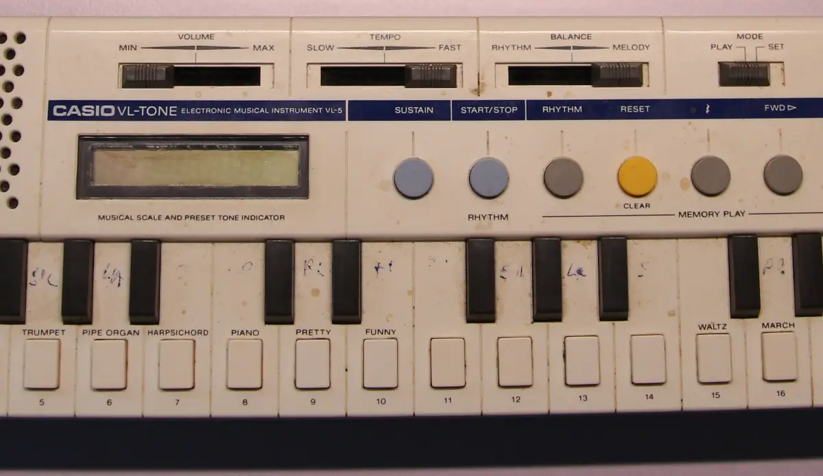
 Indeed, the VL-5 comes with 10 preset sounds that aren't editable, apart from the option to activate the Sustain function. In ADSR terms (attack/decay/sustain/release), it doesn't strictly mean the "S"; for some sounds, it effectively acts as the "R".
For instance, with the flute sound and sustain enabled, releasing the key (note off) results in a slow fade-out. Without sustain, the sound cuts off abruptly.
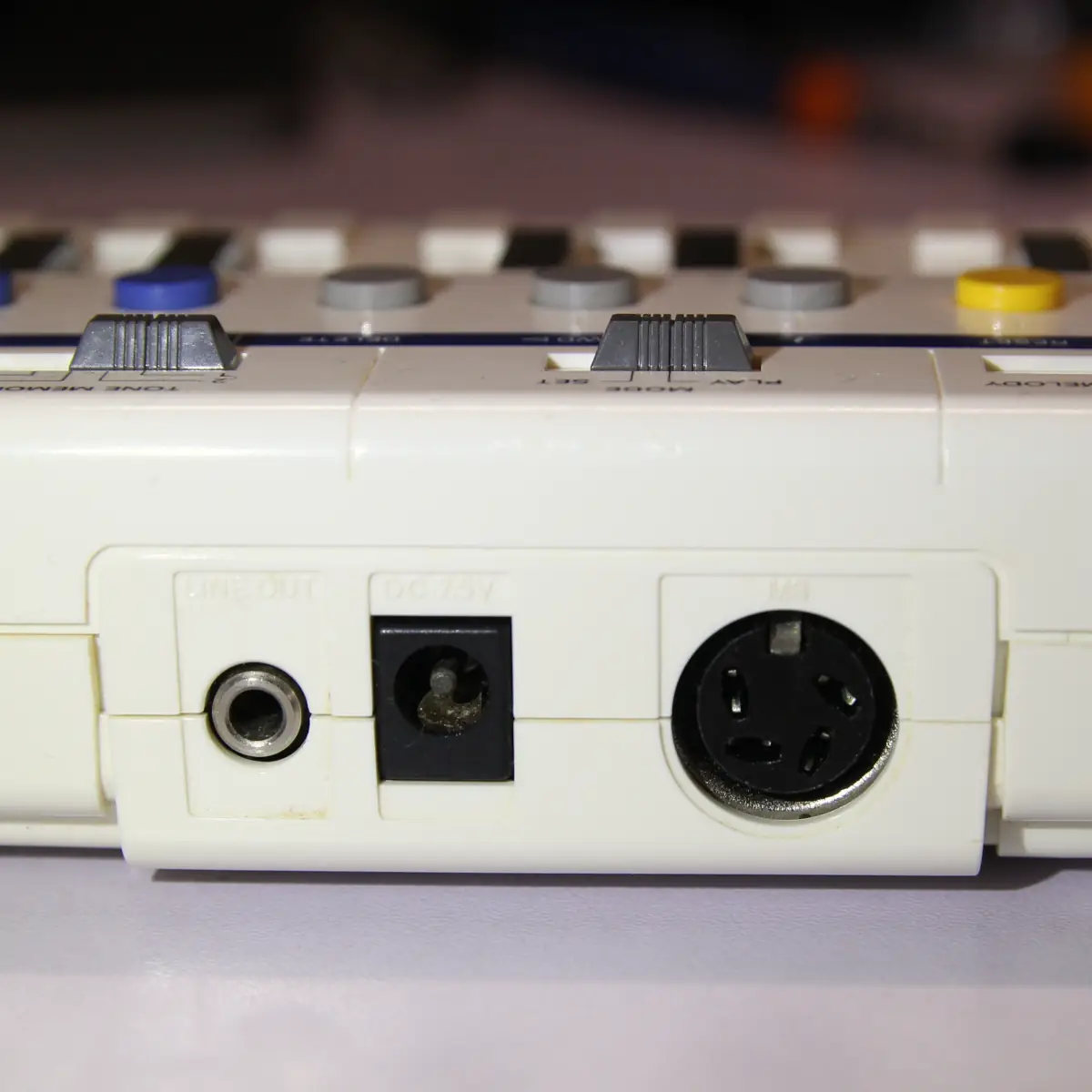
The rear panel features an external power input, a line out, and a 4-pin DIN input. Apparently, this port enables connection to a barcode reader pen for playing melodies encoded in barcodes.
What’s really cool is that there’s an article from the 1984 “Your Spectrum” magazine online, providing a detailed explanation of this interface protocol and a ZX Spectrum source code that makes its emulation possible. Once I have some free time, I’ll dive into this and play around with it a bit, assuming I can fix this keyboard first.
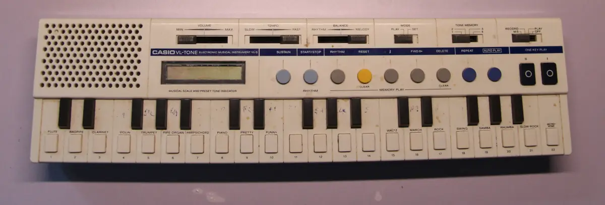
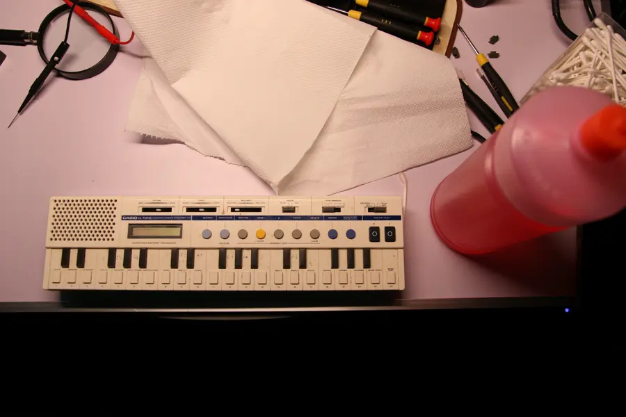
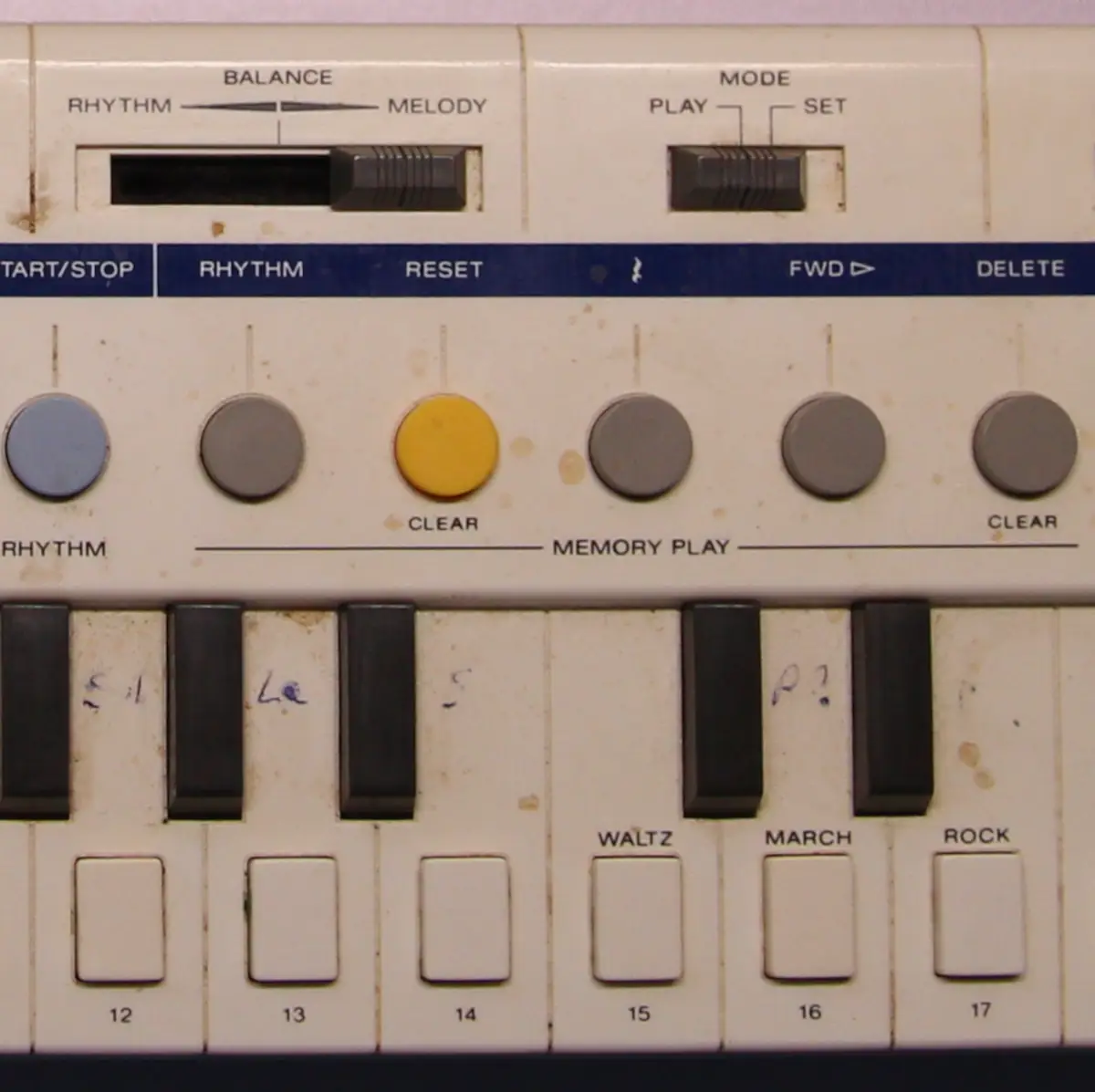
And that brings us to today’s topic: its repair and restoration. I’d seen the auction photos and knew it was well-used, but it seemed salvageable, at least aesthetically.
It arrived in quite a state: caked in grime, stains, and pen markings. I have to admit, handling it felt a bit gross, but no surprises there: I was fully aware of what I’d bought.
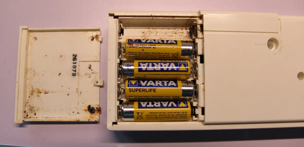
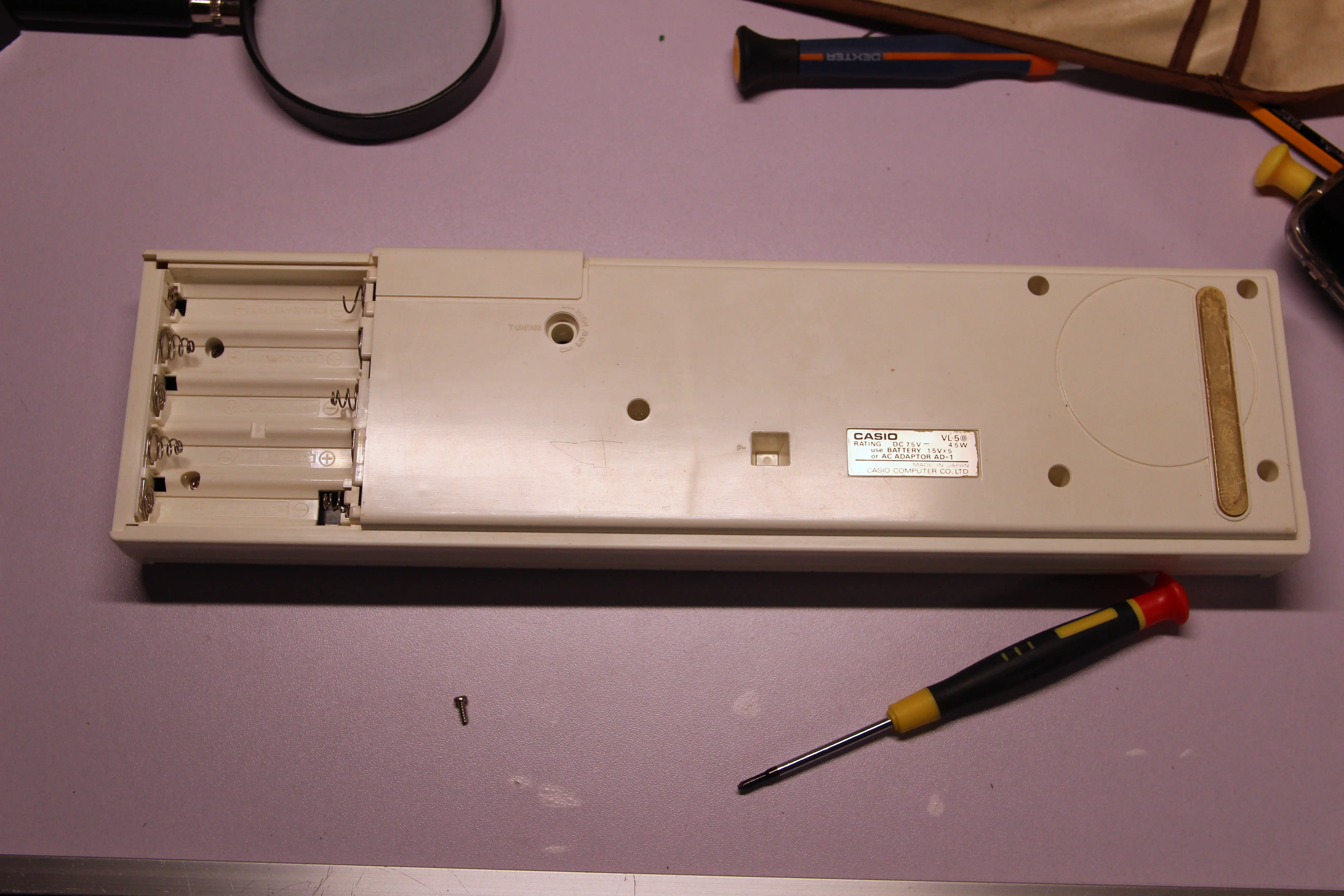
The real “surprise”, unfortunately, came when I opened the battery compartment.
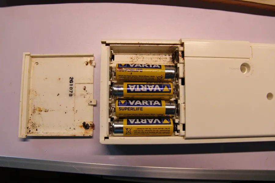 “The horror, Kurtz said at the end of Heart of Darkness, the horror. Lucky Kurtz didn’t have this battery compartment delivered in the jungle. Ugh… then he’d see some horror." (Boris Yellnikoff, semi-quote)
Batteries had been sitting in there for who knows how many years, corroding the contacts and perhaps even the internal circuit.
At this point, I was a bit discouraged, but I decided to try it with an external power supply anyway.
I was curious to figure out what was wrong with this keyboard, since, as I mentioned, it was sold to me as non-functional.
 On the back, there's a 7.5 volt power input.
However, there's a problem: the power connector's polarity isn't indicated.
I didn't want to risk inadvertently destroying any components, so I looked up some info online, and it seems the center should be negative.
It seems to be working perfectly! This seems almost too straightforward.
I fiddled with it for a bit, and everything works: it's incredible.
Who knows why the previous owner told me it wouldn't turn on.
 So, what I initially thought would be a repair magically turned into a restoration.
Let's start by removing those old, disgusting batteries.
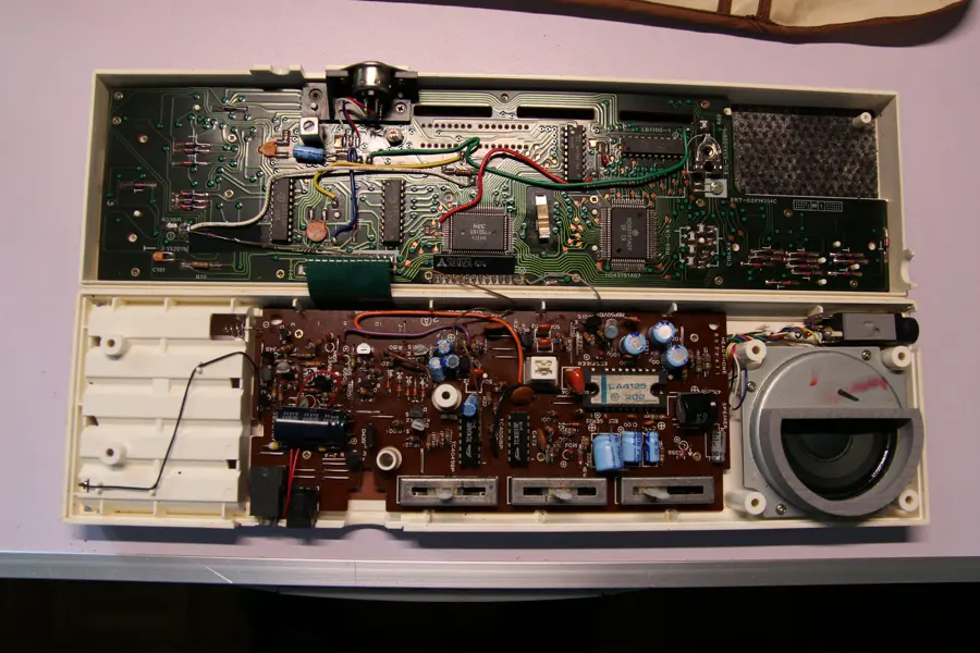 To my great delight, the inside is in pristine condition! I certainly got lucky there.
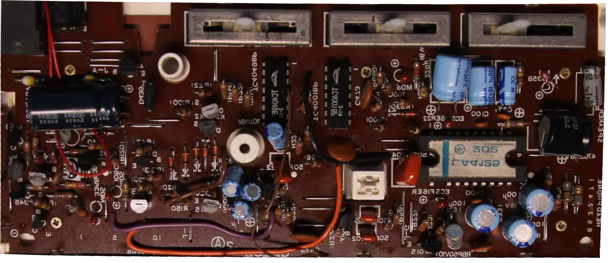
The lower board seems to contain all the analog circuitry (almost): the power supply section, an integrated circuit with 6 inverting buffers (TC4049), another IC containing 4 NOR gates (TC4001, no idea what they're for), and a power amplifier (LA4125).
The upper board, on the other hand, contains the digital core that defines this keyboard.
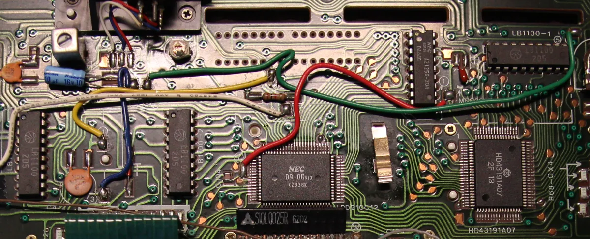
- NEC D910G: This is one of the two processors in the machine. Unfortunately, I can't find a datasheet, so I have to rely on information found online. Apparently, this processor handles sound generation, including drum sounds.
- HD43191A07: This should be another CPU, but there's no information online about its function. By elimination, I assume it manages everything else.
- NEC A21256: This is the 262,144-bit DRAM, roughly 32KB.
- 3 x LB1100: I can't find any information about these online.
I'm proceeding with cleaning the outer casing. I'll start with the battery compartment and cover.
I unscrew the lower PCB, but this isn't enough to detach it from the casing, as there are 2 wires connected to a metal plate glued to the casing itself (likely some sort of shielding), and the black wire connected to the batteries.
I'll definitely need to desolder them.
 At this point, I can submerge the compartment and the cover in my trusty ultrasonic cleaner, which I've conveniently filled with water and vinegar.
While the cleaner does its job, I want to use my ESR meter to check that all electrolytic capacitors are in good shape.
For this purpose, I'll first do a little prep work.
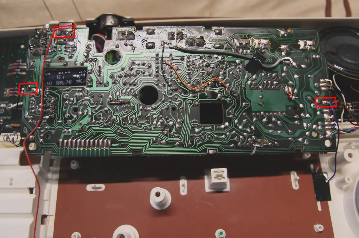
Then, still in GIMP, on a new layer, I highlight in red the points to check with the meter.
All clear, right? Okay, I realize it sounds complicated in words, but it's actually much simpler than you might think.
Below, you can see what I'm talking about more clearly: you can choose which of the 2 sides of the PCB to view and activate the highlighted red points.

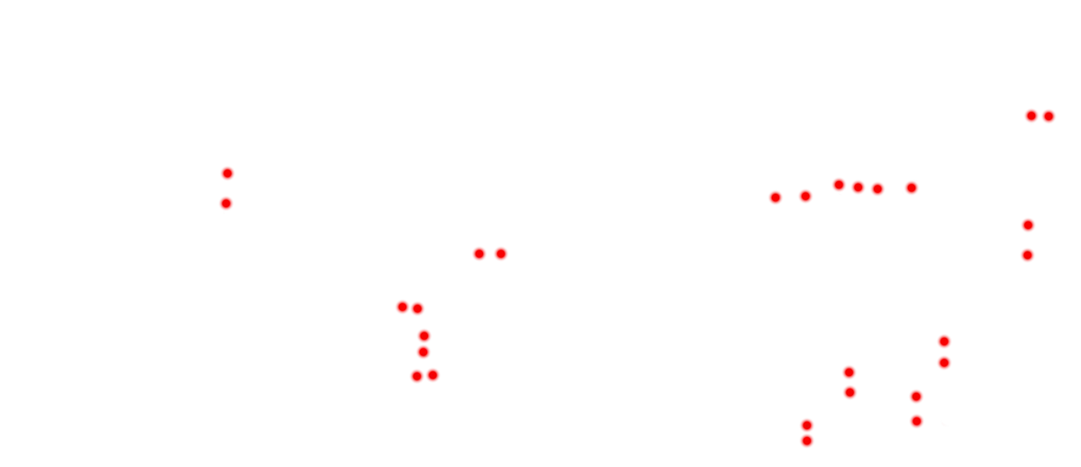
Why did I do all this? I think it becomes quite clear by selecting the "PCB - Back" layer and activating "Points to check".
Having the point diagram ready means I know exactly where to place the ESR meter probes, and I avoid constantly flipping the board to find where the capacitors are located.
Often, especially on densely packed boards, finding the exact points is incredibly difficult.
With this technique, the work becomes much easier, and I avoid going crazy!
Beyond that, and perhaps even more vital, I also avoid stressing the ribbon cable connecting the 2 PCBs and all the various wires.
In my experience, constantly flipping it back and forth eventually causes some cable to detach.
 I'm now reading the ESR value for each individual electrolytic capacitor.
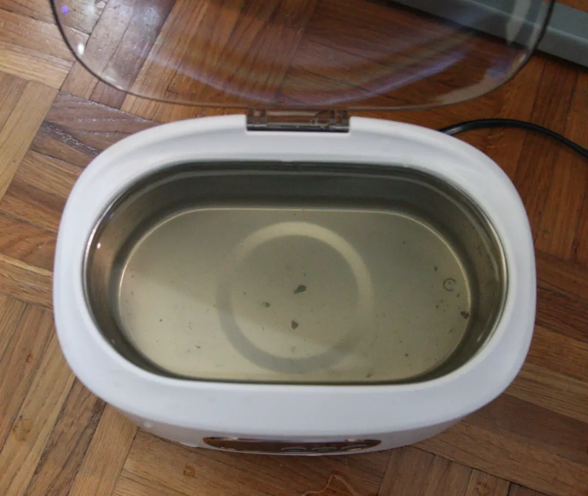 I ran the cleaner for two 10-minute cycles; look at the grime that settled at the bottom.
Afterward, I'll rinse both pieces under running water and brush away any lingering debris with a toothbrush. The result, I'd say, speaks for itself.
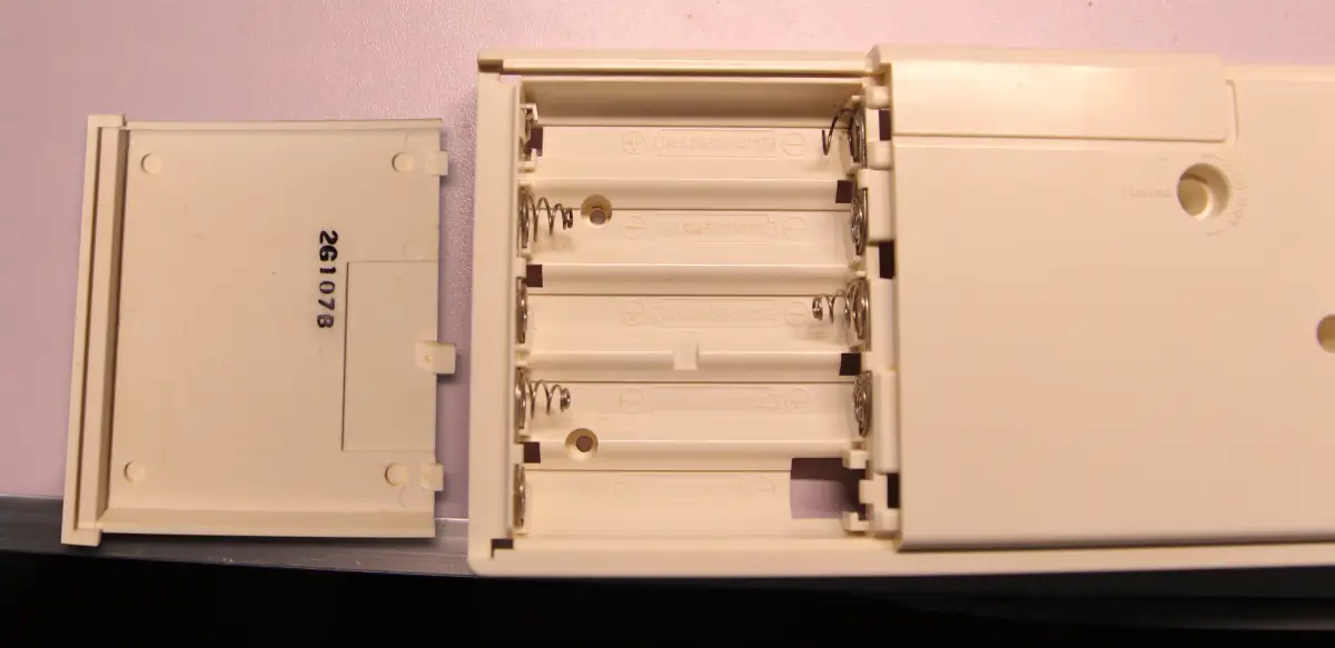
Unfortunately, the spring in the upper right was damaged by extreme corrosion and broke.
In any case, I don't think it's a major issue: I managed to re-tension it with pliers, so it should still work fine.
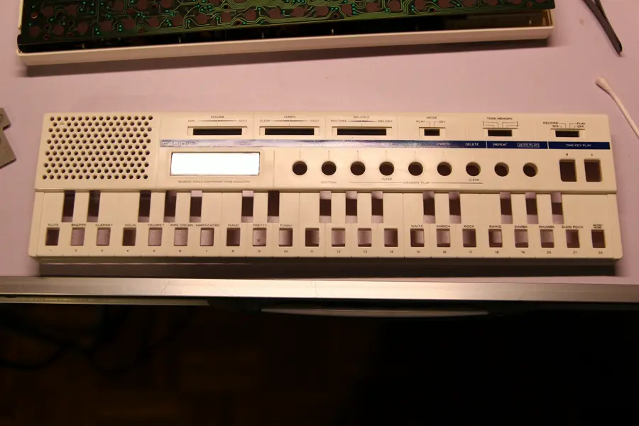
 Next, I'll clean the upper part of the keyboard, using alcohol, cotton swabs, and paper towels.
It wasn't something I was excited about, but to get a good result, It became necessary to separate the upper case from the PCB as well, so I can thoroughly brush all the harder-to-reach areas.

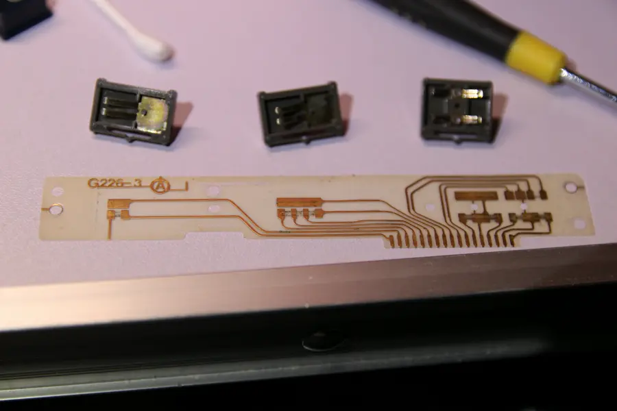 Beneath the three switches in the upper right of the keyboard lies an incredibly thin PCB, barely thicker than paper. I'll clean these contacts very gently.
 Now that the case is free, I'm heading to the bathroom to complete the brushing, with the aid of a basin full of warm water.
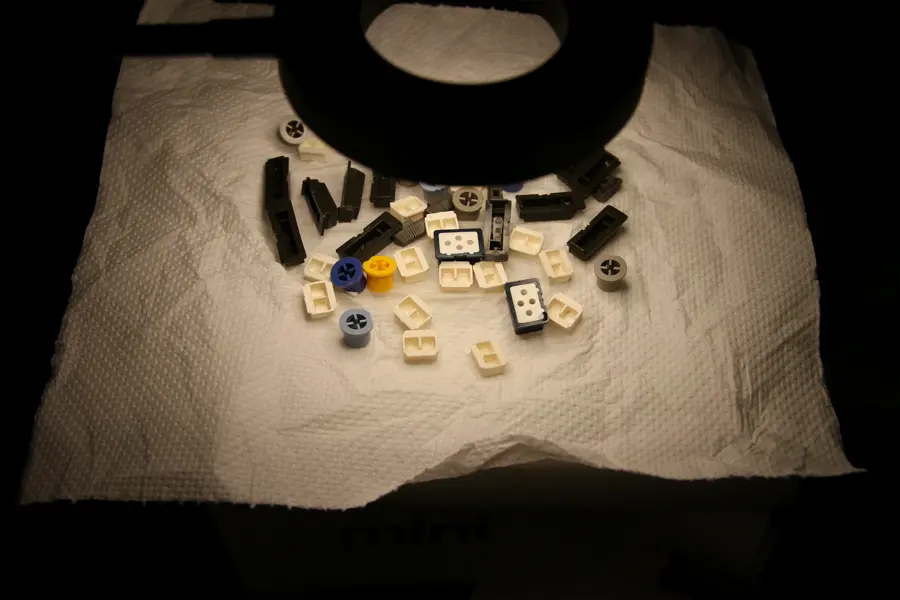
I'm putting the buttons in the ultrasonic cleaner so they can be thoroughly sanitized.
Now I’m finally 100% satisfied!
A close-up of the back of the PCB, where the buttons and liquid crystal display are located.
In a moment of distraction, I almost cleaned them with isopropyl alcohol and a cotton swab.
Fortunately, I stopped in time; otherwise, I would have destroyed the keyboard.
This is because these contacts aren’t metallic; they’re made of a special graphite. Alcohol would have removed part of that graphite, or all of it in the worst case, and then “adios muchachos”, as Paul Reiser said in Aliens.
Actually, it probably could have been recovered by rubbing a pencil (which is made of graphite) over it.

 I'm putting the buttons out to dry and then I'm off to dinner!
Finally, I can reassemble everything!
I’m thrilled with the result; it looks almost new.
What can I say? I'm very satisfied with this restoration; it turned out much better than I'd hoped.
Now, all that’s left is to do some musical experimentation.
 As I mentioned earlier, I'd like to try interfacing it with a computer, which doesn't necessarily have to be a ZX Spectrum.
We'll see! That's it for now.
It has been submitted and will be reviewed before being published.