Building a Remote Shutter for a Canon Powershot with CHDK
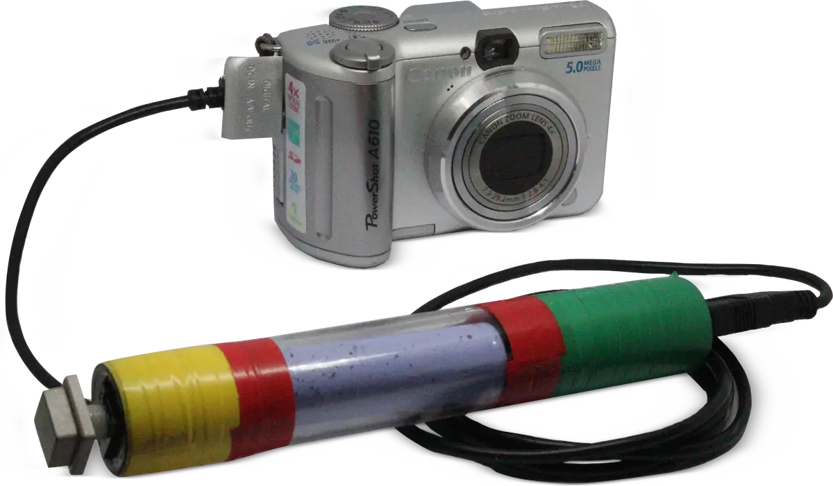 In this post, we'll see how to build a remote shutter for a Canon Powershot A610 (and a wide range of other models).
I want to experiment with a monopod and take photos from unconventional positions, such as from above. This accessory will be very useful for that purpose.
It could also be helpful for long-exposure photography, as pressing the shutter button usually causes the camera to vibrate, and even imperceptible vibrations can compromise the photo's quality.
By default, this camera doesn't support remote shooting, but there's a way to add it: by installing the CHDK firmware.
I won't go into detail about installing CHDK; for that, I'll direct you to the official website.
 How it works: by applying 5 volts (logic level 1) to the camera's USB port, you activate the "half-pressed shutter button" mode, which typically triggers the camera's autofocus and/or auto-exposure.
Once you're ready, you remove the 5 volts input (logic level 0), and the photo is taken.
Simple as that.
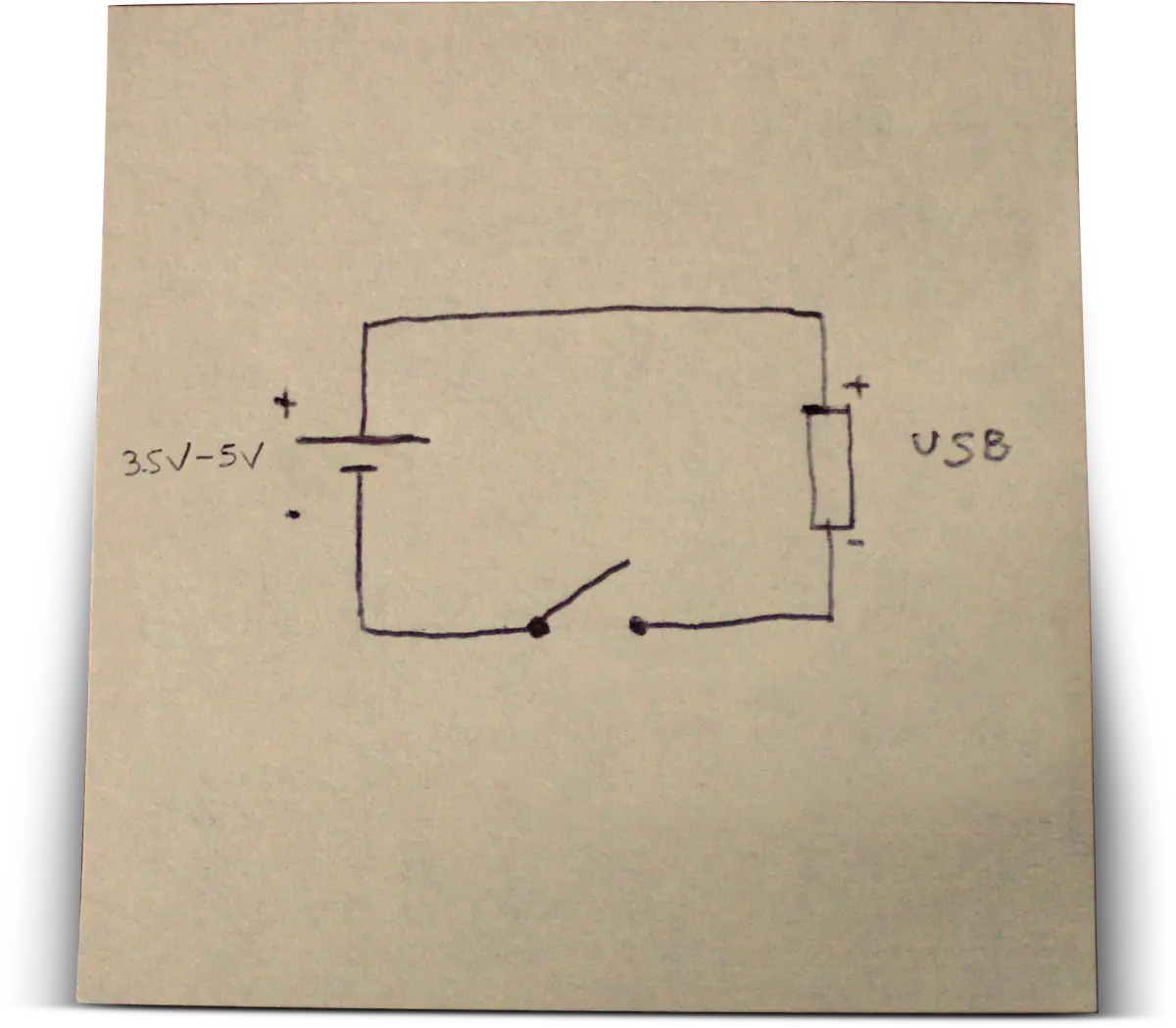
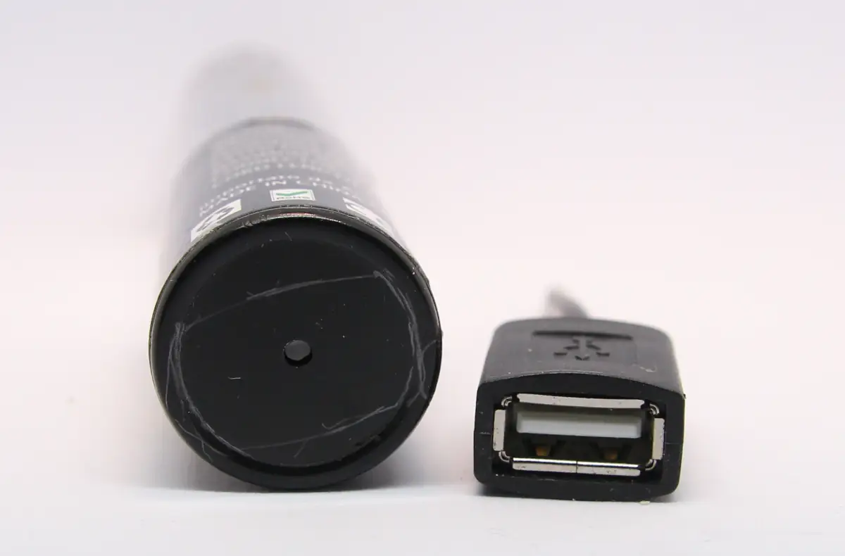
Since I’m only using salvaged parts, I need a casing, a USB connector, a button, and a 5-volt power source. To be precise, a source between 3.5 and 5 volts would be enough to achieve logic level 1.

I've already fully charged it.

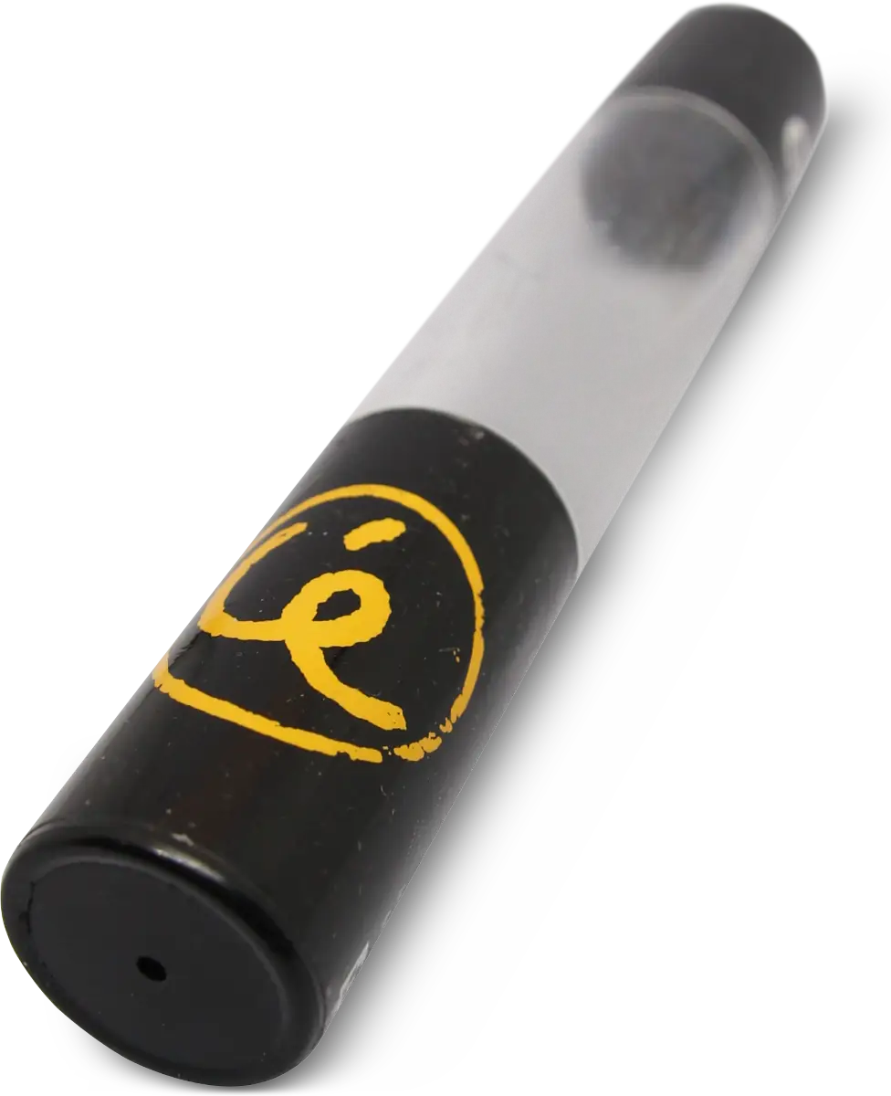
 I started by taking measurements: I traced the shape of the USB connector with a pencil on one end of the plastic tube.
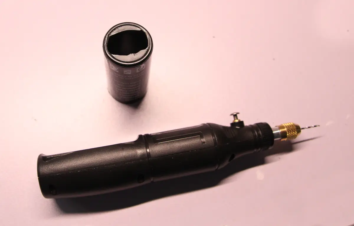 With the drill, I made the hole (very roughly) for the connector to pass through.
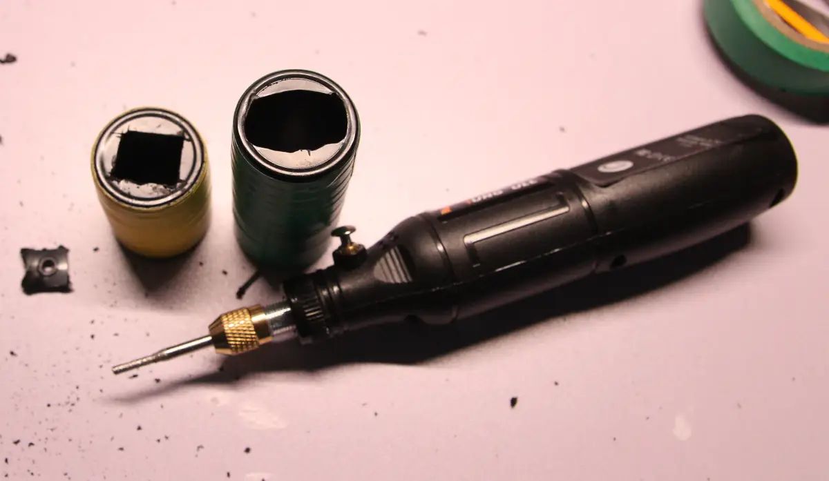 I did the same on the other end of the plastic tube: I traced the shape of the button and drilled the hole.
In the meantime, I've covered both ends with colored electrical tape to hide the markings.
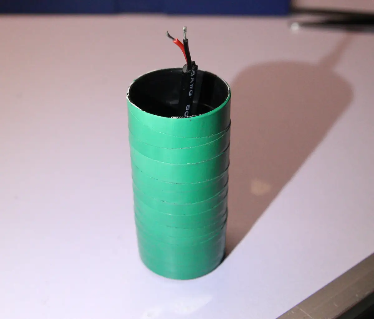 I stripped the connector cable to expose the red and black wires, and then positioned it inside the end of the plastic tube.
 I poured hot glue inside the tube to secure the connector.
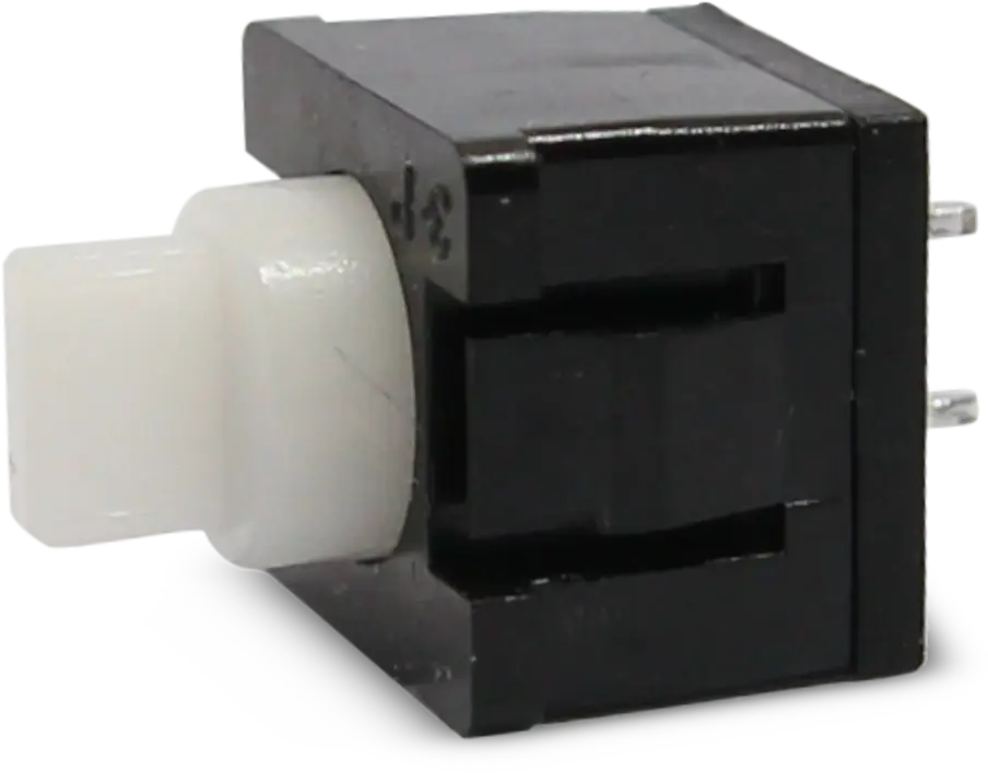
 I soldered two wires to the terminals of the switch.
 I inserted the switch into its part of the tube. It's not necessary to use hot glue here, as the button is held in place by its two side clips.
I soldered the red wire from the USB connector to the positive terminal of the battery, and the black wire to one of the switch’s terminals.
Then, I soldered the second terminal of the switch to the negative terminal of the battery.
I inserted a small piece of polyurethane to create padding and secure the battery inside the tube; then I closed everything up.
I sealed it all with red electrical tape, and as a final touch, I placed its cover button onto the switch. Assembly complete!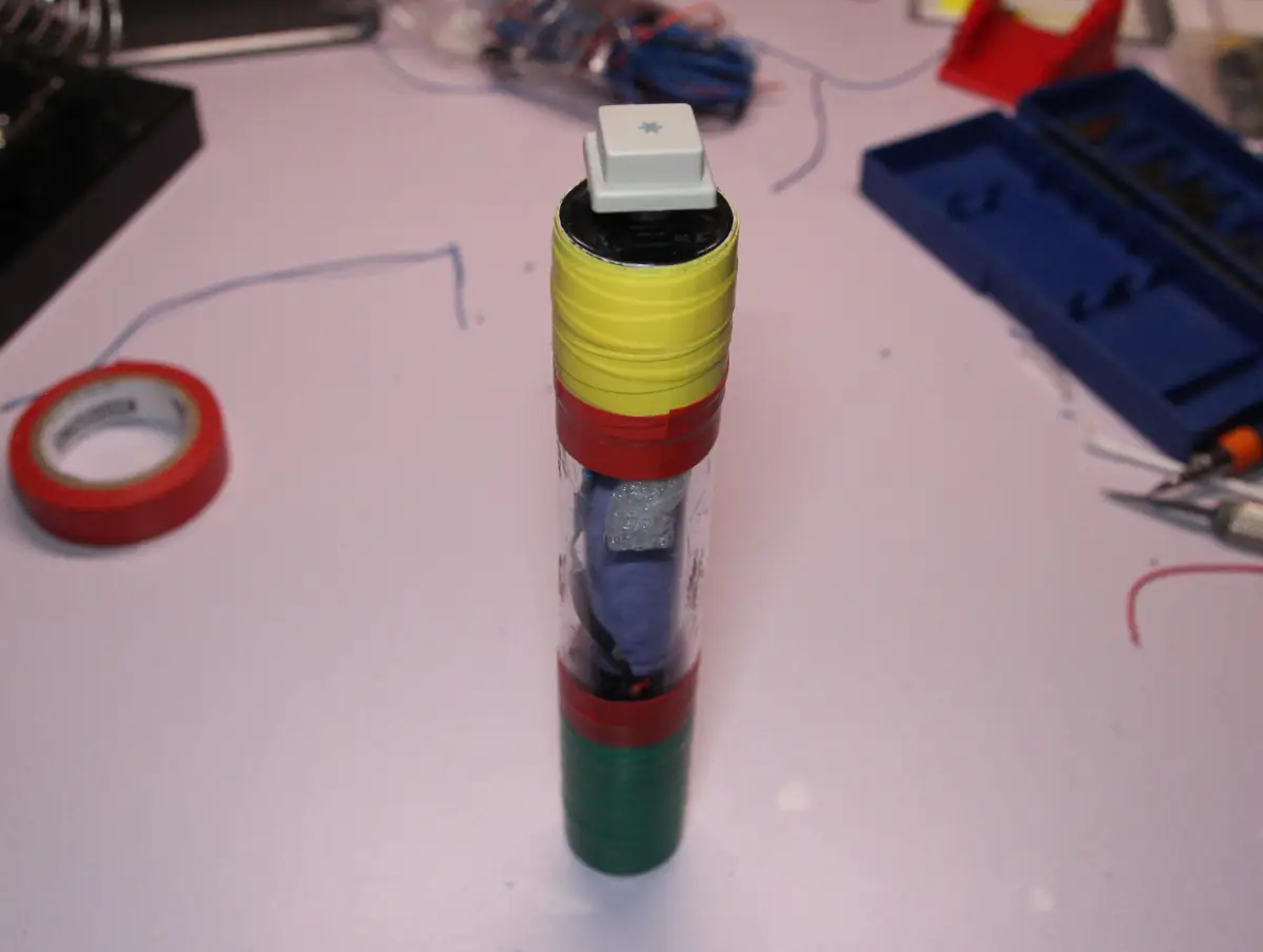
It works perfectly.
The battery will probably never need recharging, given its minimal power consumption.
In the event it needs recharging, you can connect it to any 5-volt USB source; just make sure to hold the button down to close the circuit (I was thinking of an elastic band, for example).
It might not be pretty, but I built it for free, and it does exactly what it’s supposed to do.
That’s it for now.
It has been submitted and will be reviewed before being published.